
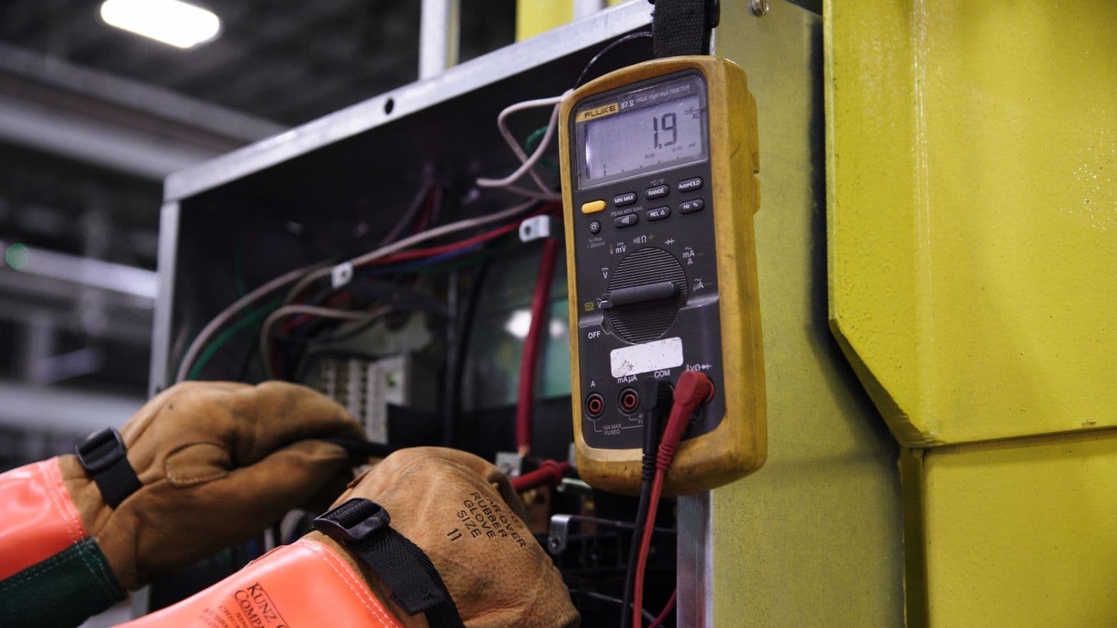
Once a panel is handed over, most facility owners never think about opening the door again, until a fault occurs. At that moment, the maintenance staff on site either have an accurate test report and labelling in hand, or they're forced to guess which circuit is which. Panel testing and labelling may look like the "last step" of the manufacturing process, but it's actually the foundation of both safe operability and legal defensibility after an incident. A meaningful share of panels handed over across Bursa's OIZs arrive with missing or superficial test reports, and labelling that was never updated as work on site grew. This article covers the testing that should happen before handover, labelling standards, and what skipping these steps actually means for both safety and liability.
Why Testing and Labelling Are Each Critical, Separately
Testing proves the panel is electrically correct and safe at the moment of handover; labelling ensures that safety holds up over time. Even a perfectly tested panel becomes a liability three years later if maintenance staff don't know which breaker belongs to which circuit during a fault, they can isolate the wrong circuit and start working on one that's still live. This is one of the most common causes of electrical accidents in practice. Testing proves safety at handover; labelling preserves that safety across the panel's operating life. Together, they're the evidence that a panel was both "manufactured correctly" and "can be operated safely."
Type Test vs. Routine Test
Under TS EN 61439-1, there are two distinct verification levels. Design verification proves, once, that the panel's reference design conforms to the standard, through tests or calculations covering enclosure withstand, thermal performance, and short-circuit withstand. Routine verification is the set of checks that must be performed individually on every single panel coming off the production line. A flawless type-test report doesn't mean every unit in that production run was assembled flawlessly, routine tests catch the individual errors that can occur during assembly, like a loose connection, a reversed phase, or a missing ground. We cover this distinction in more depth in our TS EN 61439-1 article.
Insulation Resistance Testing
Insulation resistance testing verifies there's adequate electrical insulation between live conductors and earth, and between different phases. The test is usually performed with a megohmmeter applying 500V or 1000V DC, and the measured resistance is expected to exceed the minimum value specified in the applicable standard. Low insulation resistance can stem from moisture, contamination, mechanically damaged cable insulation, or conductors pinched or nicked during installation. This test must be done before the panel is energized, because a panel energized with low insulation resistance directly raises the risk of leakage current, ground faults, or phase-to-phase short circuits. Results should be recorded per circuit and attached to the handover report.
Functional Testing
Functional testing proves the panel operates as designed through direct observation: breaker open/close operation, contactors engaging in the correct sequence, protection relays tripping at their set values, and signal lamps and fault indicators working correctly. In MCC panels, this test includes confirming each motor output is wired to the correct motor, that overload relay settings match the motor's nameplate current, and that emergency stop (E-stop) circuits actually shut down all relevant outputs. In panels with automation integration, this stage should also confirm that PLC commands trigger the correct relay/contactor and that feedback signals are read correctly. When functional testing is skipped, a panel that looks correct on paper but doesn't work on site shows up at first energization, usually meaning a delayed production start.
Continuity and Protective Conductor Testing
Verifying that the protective (earthing) conductor runs uninterrupted from every point in the panel to the enclosure and ultimately to the main earthing system is a precondition for a residual current device (RCD) to function correctly. Continuity testing, done with a low-resistance test instrument, confirms the resistance between the ends of the protective conductor falls within standard limits. The panel's connection to the overall earthing system should also be verified as part of earthing measurement, even if continuity within the panel is fine, if the earthing system the panel connects to is inadequate, protection can't fully do its job.
Documenting Short-Circuit Withstand
For main distribution and transformer-feeder panels, documentation showing the panel's short-circuit withstand current (Icw) meets the grid fault power calculated at the design stage is a mandatory part of the handover file. This documentation comes not from physical testing of the panel itself but from the short-circuit calculation and the panel's type-test/calculation report; still, at handover these two documents (grid fault power and the panel's Icw rating) need to be checked against each other for consistency. Skip this check and a serious mismatch, the panel's short-circuit withstand sitting below the grid's actual fault power, can go unnoticed until it matters.
Labelling Standards: Circuit Identification
Every breaker, contactor, and feeder needs a label that matches its identity in the panel's single-line diagram exactly, not a generic name like "Motor 1," but a description that clearly states which equipment and which location it feeds. Labels should be made of a permanent material (engraved or durable print) that won't fade or peel over time, labels handwritten on paper and taped on become unreadable within a few months. Good labelling practice includes:
- A circuit number and the fed equipment's name on every breaker/contactor
- The same identity number on both ends of every incoming and outgoing cable
- A label on the outside of the panel stating the general supply source (which transformer/main panel)
- Rated current and protection settings noted on or near each feeder's label
Warning Labels and Hazard Signage
Labelling isn't just about identification, it also serves a safety-warning function. Typical warning labels a panel should carry: voltage level warning, "authorized personnel only" warning, dual-supply warning where more than one supply source exists (for instance, potential generator backfeed), and arc-flash warning labels on panels carrying high short-circuit current risk. In panels with dual supply or an automatic transfer switch (ATS) in particular, a warning that disconnecting one line doesn't guarantee the circuit is dead, the other source may still keep it live, is one of the most basic ways to keep maintenance staff from accidentally working on an energized circuit.
Single-Line Diagram: Physically Attached to the Panel
The panel's current single-line diagram must be physically present, mounted on the inside of the door or in a pocket near it, not just stored digitally in a project file, which isn't accessible on site during a fault. The single-line diagram shows the source, protection device, and fed load for every circuit in the panel; it's the reference point for both maintenance and future modification/expansion work. Every subsequent change to the panel (a new feeder added, a breaker swapped) must also be reflected in the single-line diagram, a diagram that's never updated gradually becomes a document that no longer reflects reality, and can actively mislead.
What a Proper Test/Handover Report Should Include
A complete panel handover report should contain:
- General panel information: Manufacturer, serial number, manufacture date, applicable standard (TS EN 61439-1/2).
- Design verification summary: Which reference design the panel is based on, and how thermal and short-circuit withstand verification was performed.
- Routine test results: Insulation resistance, continuity, and functional test records per circuit.
- Protection coordination summary: Breaker/fuse settings and selectivity assessment.
- Labelling checklist: A signed checklist confirming every circuit and warning label is in place.
- Single-line diagram: The panel's current state as of handover.
- Declaration of conformity: A signed document declaring conformity to the applicable standard.
Completeness of this report matters not only for operational safety but also because it's the single concrete document proving the panel was correctly manufactured, should a future audit or insurance claim ever require it.
Common Mistakes
- Testing insulation resistance only on the main incoming supply and skipping outgoing feeders: Weak insulation on one outgoing feeder may not show up in the main measurement.
- Making labels from temporary material (paper, handwriting): These become unreadable within a few months and can lead to isolating the wrong circuit during maintenance.
- Not physically attaching the single-line diagram to the panel: A digital file isn't accessible on site during a fault.
- Not updating labels and the diagram after modifications: Over time this creates a mismatch between documentation and the panel's actual state, one of the most dangerous scenarios possible.
FAQ
Can a panel be commissioned without a test report? Technically it can be energized, but this carries a real safety risk and creates serious problems during OIZ/audit processes and any insurance claim. A panel without a test report can't prove conformity to the applicable standard.
Is routine testing done on every panel, or by sampling? Under TS EN 61439-1, routine verification is a requirement performed individually on every single panel coming off the line; sampling does not substitute for routine testing.
What standard governs labelling? There isn't one single definitive labelling standard, but the general marking requirements under TS EN 61439-1 combine with the facility's own internal safety procedures; what matters most is consistency and legibility.
Which panels require arc-flash warning labels? While the exact requirement isn't defined identically everywhere, this label is strongly recommended on main distribution and transformer-feeder panels carrying high short-circuit current, so maintenance staff know the risk level in advance.
Can testing and labelling be done retroactively on an old panel? Yes, and it should be. Continuity and insulation resistance tests and labelling can be completed later on older panels with missing documentation; but if the panel is found to be structurally non-compliant, testing and labelling alone may not be enough, replacement should be considered in that case.
Who should sign the test report? It should be signed by the authorized technician who performed the testing and by the EMO-registered electrical engineer responsible for the panel's conformity.
What happens if a fault is found during functional testing? The fault is corrected and the relevant test is repeated; the corrective action and retest result should be separately noted in the handover report.
How long should the handover report be kept? It should be kept for the panel's entire service life; it's one of the first documents requested during periodic inspections and in any accident investigation.
Testing and labelling aren't the final touch on a panel's manufacturing process, they're the last, mandatory step in making a panel safe to operate. A handover that skips this step may look like it saves time in the short run, but it turns into a far larger cost at the first fault or the first audit. Our LV panel installation service delivers every panel with a complete test and labelling report.
Let's talk through this together
The SOREAS engineering team can assess what's covered here for your specific facility. Reach out via the contact form or call us directly.