
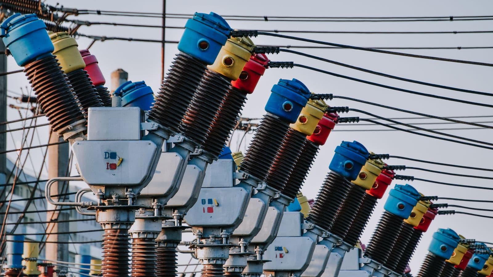
An unexpected power transformer outage means the entire facility stops producing, and most transformer faults actually give early warning signs that could have been caught weeks or even months in advance. Most of the faults our field teams encounter across Bursa's organized industrial zones are problems that regular thermal inspection and oil analysis could have flagged ahead of time, and that scheduled maintenance could have prevented. This article covers the 7 most common transformer faults, along with the cause, warning signs, and fix/prevention approach for each. The goal is to help you recognize these signs before they turn into an unplanned shutdown.
1. Overheating and Insulation Degradation
Cause: Overloading, insufficient cooling (blocked radiator, faulty fan), high ambient temperature, or additional heating from harmonic loads can push winding temperature above the limits defined in IEC 60076-1:2011. Sustained high temperature accelerates chemical breakdown of the winding insulation (thermal aging), as a general rule of thumb, every sustained 8-10°C rise in temperature roughly halves insulation life.
Warning signs: Above-normal hot spots on thermal camera images, abnormal heating on the transformer body, frequent oil-temperature alarm triggers in oil-immersed units, winding temperature sensor warnings in dry-type units.
Fix/prevention: Periodic thermal camera scans, regular cleaning and functional testing of the cooling system (radiator, fan), correctly sizing transformer capacity to the actual load profile, and filtering harmonic sources (VFDs, rectifier loads) per IEC 61642.
2. Oil Contamination and Moisture Ingress
Cause: Gaskets hardening and leaking over time, breather desiccant becoming saturated, or a compromised tank seal all allow atmospheric moisture into the oil. Moisture lowers the oil's dielectric strength and accelerates acid formation that reacts with and weakens winding insulation.
Warning signs: Cloudiness or darkening in an oil sample, low results on a dielectric strength test, rising moisture/gas values on a DGA (Dissolved Gas Analysis) test, and color change (blue to pink) in silica gel breathers.
Fix/prevention: Periodic oil analysis (moisture, dielectric strength, DGA), gasket and seal inspection, regular replacement of breather desiccant, and oil filtration or vacuum drying when needed.
3. Bushing Failures
Cause: Bushings are the critical components that insulate the high-voltage feed-through between the interior and exterior; they can degrade over time from contamination (dirt, salt, industrial dust buildup), surface cracking, partial discharge within internal insulation layers, or a loose connection. A bushing failure often manifests suddenly and severely.
Warning signs: Visible contamination or cracking on the bushing surface, abnormal heating at the bushing connection point on thermal camera, increased activity on a partial discharge measurement, and deviation on a bushing tap (capacitance) test.
Fix/prevention: Periodic visual inspection and cleaning, torque-checking bushing connection points, monitoring insulation condition via capacitance/loss factor (tan delta) tests, and selecting bushings with appropriate creepage distance for highly contaminated environments.
4. Tap-Changer Issues
Cause: The tap changer is a mechanical/electrical system that adjusts the transformer's winding ratio for voltage regulation. Frequent tap changes cause mechanical wear on contacts, carbon buildup, and rising contact resistance. In oil-type tap changers, the arc generated during switching contaminates and carbonizes the oil locally.
Warning signs: Abnormal noise or delay during a tap change, accelerated contamination in the tap changer's oil compartment (where a separate tank exists), rising contact resistance measurements, and inconsistent behavior in automatic voltage regulation.
Fix/prevention: Periodic maintenance (contact cleaning/replacement) based on the manufacturer's specified tap-change count, separate and more frequent analysis of tap-changer oil, and lubrication and wear inspection of mechanical parts.
5. Cooling Fan and Radiator Faults
Cause: In forced-cooled transformers (ONAF, OFAF), fan motors can fail over time due to bearing wear, electrical fault, or dust accumulation. On radiators, dust/dirt buildup on the exterior surface or sludge formation in internal channels reduces heat-transfer efficiency. One or more failed fans prevents the transformer from operating safely at full capacity.
Warning signs: Abnormal vibration or noise while a fan is running, reduced fan speed, uneven temperature distribution on the radiator surface via thermal camera, and faster-than-expected temperature rise under load.
Fix/prevention: Periodic functional testing and bearing inspection of fan motors, regular cleaning of radiator surfaces, an oil circulation test if internal sludging is suspected, and spare-fan/redundancy planning at critical facilities.
6. Winding Insulation Breakdown
Cause: Prolonged overheating, repeated exposure to short-circuit forces (especially at facilities experiencing frequent grid-side faults), degraded oil/moisture quality, or a manufacturing defect all cause winding insulation to lose mechanical and electrical strength over time. This is typically the most serious and costly fault type, as it often requires rewinding or transformer replacement.
Warning signs: Detection of high-energy fault gases such as acetylene (C2H2) on a DGA test, a marked drop in insulation resistance measurement, a low result on a polarization index (PI) test, and sudden, repeated protection relay tripping during operation.
Fix/prevention: Periodic insulation resistance and DGA testing, correctly configured protection coordination based on the short-circuit calculation (see our short-circuit calculation guide), monitoring grid-side fault frequency, and periodic insulation condition assessment on aging transformers.
7. Protection Relay Misoperation
Cause: While the protection relay does not directly protect the transformer's physical structure, a misconfigured, miscalibrated, or faulty relay fails to protect the transformer during an actual fault, or trips the circuit unnecessarily, causing an unplanned shutdown. Incorrect selectivity settings can cause an upstream protection device to trip along with a downstream fault.
Warning signs: Relay test results deviating from factory settings, unexplained or unnecessary trips, outdated relay manufacturer firmware, and inconsistent trip timing on annual functional tests.
Fix/prevention: Periodic relay function and calibration testing, keeping the protection coordination study current (especially after any load or topology change at the facility), and verifying that relay settings remain aligned with the short-circuit calculation.
Fault Cost: Planned Maintenance vs. Unplanned Downtime
The true cost of a transformer fault is not limited to the repair or replacement bill. An unplanned shutdown brings in production loss, delivery penalty clauses, high emergency freight and labor costs, and in some cases the cost of renting a backup transformer, the sum of these items often dwarfs the annual cost of a scheduled maintenance program many times over. A bushing failure, for instance, can be resolved during planned maintenance with a few hours of downtime and a mid-cost part replacement; the same fault occurring suddenly and severely can damage adjacent equipment and turn into a shutdown lasting days. That's why investment in a periodic maintenance program pays for itself within a few years at most facilities.
What These 7 Faults Have in Common: Early Detection
Nearly all of the faults above develop gradually, not suddenly, periodic checks such as thermal camera scans, oil analysis, insulation resistance measurement, and relay testing can catch them weeks or even months in advance. This is why preventing transformer faults depends largely on a disciplined, regularly scheduled maintenance program. We cover the scope and frequency of this program in detail in our substation periodic maintenance guide.
When Is Emergency Expert Support Needed?
When any of the signs above are observed, correctly classifying the severity of the issue is critical. Findings such as a few degrees of deviation on a thermal camera or a slight rise in oil moisture can usually be addressed at the next scheduled maintenance visit and don't require emergency response. By contrast, findings such as acetylene detection on a DGA test, repeated unnecessary protection relay trips, a visible crack on a bushing, or frequent oil-temperature alarm triggers are emergencies requiring same-day expert evaluation. Making this distinction correctly avoids unnecessary production stoppages while ensuring a real risk isn't left unaddressed, which is why field staff should know exactly who to call for which finding, as part of a written escalation procedure.
Common Mistakes
- Running oil analysis only once a visible problem appears: Tests like DGA are designed to give early warning before any visible symptom exists; a purely reactive approach defeats the purpose of early detection.
- Running a thermal camera scan while load is low: Overheating issues usually appear under full load; a scan done at low load can give a misleadingly "normal" result.
- Not treating tap-changer maintenance as separate from general transformer maintenance: The tap changer has its own oil compartment and wearing mechanical parts, requiring a dedicated maintenance schedule.
- Not updating protection relay settings after a facility change: Adding new equipment or increasing load can invalidate the existing protection coordination.
FAQ
How long does it take to repair a transformer fault? It depends on the fault type, a bushing or fan fault can be resolved within days, while winding insulation breakdown can require rewinding or replacement that takes weeks.
How often should a DGA test be performed? General practice is at least once a year for critical transformers, and more frequently (every 6 months) for aging units or ones operating under high load.
How often should a thermal camera scan be performed? As part of the periodic maintenance program, usually once or twice a year, preferably while the transformer is under full load.
Can a transformer fault always be detected in advance? Most faults develop gradually and can be caught early, but some situations, such as short-circuit forces from a sudden grid-side fault, may not be predictable in advance.
If the oil darkens, should the transformer be taken out of service immediately? No, the first step is to take an oil sample and have it analyzed; filtration, replacement, or simply continued monitoring is decided based on the results.
Do all 7 of these faults apply to dry-type transformers too? Items such as oil contamination and the tap-changer oil compartment are specific to oil-immersed units; overheating, bushing failure, fan/cooling issues, winding insulation breakdown, and relay misoperation can occur similarly in dry-type transformers.
Which tests should be combined for fault detection? A comprehensive assessment should combine thermal camera scanning, oil analysis (for oil-immersed units), insulation resistance measurement, and relay function testing, no single test method covers every fault type.
Should an old transformer be refurbished or replaced? This decision should be based on aging test results (DGA trend, insulation resistance, PI test) and the transformer's remaining economic life, it should rest on concrete measurement data rather than a general rule.
What percentage of transformer faults can periodic maintenance prevent? Rather than quoting an exact figure, it's more accurate to say that because most of the 7 fault types above develop gradually, regular thermal inspection, oil analysis, and relay testing can catch and address a significant share of them before they escalate into a more serious failure.
Conclusion
The vast majority of transformer faults develop gradually rather than suddenly, and a properly designed periodic maintenance program can catch and prevent them before production stops. For facilities in Bursa, regularly monitoring these seven fault types significantly reduces both unplanned downtime risk and emergency repair cost. SOREAS, with our team of EMO-registered engineers, runs periodic maintenance programs covering thermal inspection, oil analysis, and protection testing under our MV switchgear and transformer systems service.
Let's talk through this together
The SOREAS engineering team can assess what's covered here for your specific facility. Reach out via the contact form or call us directly.