
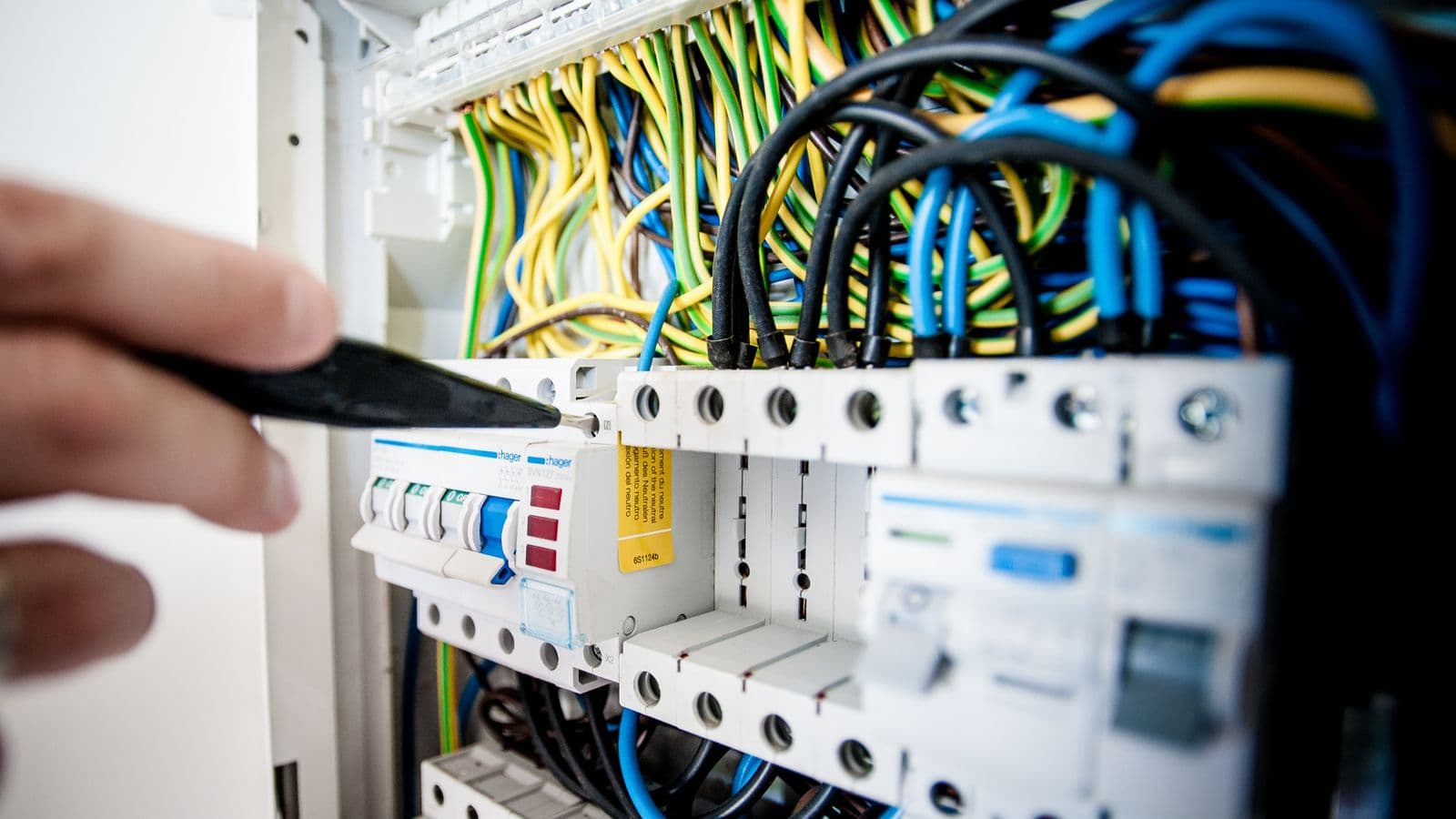
A minor fault on a single motor feeder in a factory can, under a poorly coordinated protection system, trip the main breaker feeding the entire plant, halting the whole production line over a problem that only concerned one sub-circuit. This is the most concrete and most expensive consequence of missing protection coordination, or selectivity. Even when protective devices (fuses, breakers, relays) are correctly selected, the system isn't reliable unless the time and current grading between them is properly established. This guide explains what protection coordination means, why cascading trips are so costly, how selectivity is achieved, and how this work relates to the short-circuit calculation.
What Is Protection Coordination (Selectivity)?
Protection coordination is the practice of setting protective devices (fuses, breakers, relays) at different levels of an electrical installation so that, during a fault, only the device closest to the fault opens while devices upstream remain closed. This property is called selectivity. In a selective system, a fault on a circuit fed from a sub-distribution panel trips only the small breaker feeding that circuit; the main panel and every other circuit keep running uninterrupted. Without selectivity, "non-selective tripping" occurs: an upstream device opens before, or together with, the device closest to the fault, and an unnecessarily large section of the plant loses power.
Why Are Cascading Trips So Bad?
The cost of a non-selective trip goes well beyond "the lights went out." In industrial facilities it produces:
- Unnecessarily wide production stoppages: a fault on a single motor or circuit takes unrelated production lines down with it, a direct hit to output and delivery schedules.
- Damage to sensitive equipment from abrupt outages: PLCs, servers, and precision measurement equipment can suffer data loss or hardware damage from unplanned sudden power loss.
- Harder fault diagnosis: when multiple breakers trip at once, maintenance teams take longer to locate the true source, since it isn't immediately clear which device tripped as a genuine protective response and which tripped unnecessarily.
- Erosion of confidence over time: frequent wide-area outages erode confidence in the electrical infrastructure, and the response is often to swap out equipment rather than fix the underlying coordination problem.
Achieving Selectivity: Time Grading
The most common selectivity method is time grading. The protective device at the lowest level of the installation is set with the shortest tripping delay, and delay increases progressively at each level upstream. This way, even though fault current flows through every protective device simultaneously, the lowest-level device opens first and clears the fault; upstream devices, seeing the current disappear once the lower level has opened, never need to trip. The drawback is that fault clearing takes longer for faults closer to the top of the hierarchy, so in systems with many grading levels, total tripping time at the highest level must be checked against equipment and cable withstand limits.
Achieving Selectivity: Current Grading
The second method is current grading. Here, protective devices at different levels are set to trip at different current thresholds, the downstream device trips at a lower current threshold, while the upstream device only responds to higher-current faults within its own zone. This works well where there's a sufficiently large difference in short-circuit current between devices (for example, between the transformer outlet and a distant distribution panel); but where current levels are close together (such as two grading levels immediately below the same busbar), current grading alone may not provide enough separation. In these cases, time and current grading are combined into a hybrid approach.
Breaker Tripping Curves and Coordination Logic
Most protective devices operate on a current-time characteristic curve: the higher the current, the faster the device trips. To establish selective coordination, the tripping curves of two consecutive levels must be plotted so they never intersect across the full range of possible fault currents, the downstream curve must stay below the upstream curve at every current value. For fuses, these curves are fixed by the manufacturer; for electronically protected breakers with adjustable relays, the time delay, current threshold, and characteristic curve type (standard inverse, very inverse, extremely inverse) are selected by the project engineer and set on site.
The Link to Short-Circuit Calculation
Protection coordination cannot be done independently of the short-circuit calculation. Coordination work relies on the maximum and minimum short-circuit current values at different points in the facility: the maximum current confirms that devices have adequate breaking capacity, while the minimum current guarantees the protective device will actually trip even in the most remote and weakest fault scenario. Without these two values, coordination work rests on assumptions alone and gives unreliable results on site. We cover how the short-circuit calculation is performed and why it's mandatory for nearly every MV/HV facility in our short-circuit calculation guide; protection coordination is a direct downstream consumer of the results defined in that guide.
Where Coordination Work Fits in the Project Process
Protection coordination work is an inseparable part of the project file prepared under our electrical design service. The work typically follows these steps:
- Gather the facility's single-line diagram and the technical data (breaking capacity, adjustable ranges) of every protective device.
- Calculate the maximum and minimum short-circuit currents at different points.
- Plot every protective device's tripping curve on a common graph, using coordination software or manual plotting.
- Check whether any curves intersect; if they do, revise settings (time delay, current threshold).
- Report the results, along with clearing times and the chosen setting values, and attach them to the project file.
Differences Between LV and MV Grading
On the low-voltage side, coordination is typically established between fuse-fuse or fuse-breaker pairs, based on selectivity tables published by the manufacturer, valid only for the specific device combinations tested in a lab, mixing devices from different manufacturers can void the selectivity guarantee. On the medium-voltage side, coordination is established between adjustable protection relays using IDMT (inverse-time) curves, more flexible but requiring more engineering calculation; as long as the same IEC-standard curve type is selected, coordination remains reproducible even across different relay manufacturers. At a facility with its own substation, MV-side coordination must also be compatible with the utility's or OIZ's main breaker, coordination work then extends beyond the facility's boundaries and typically needs to be cross-checked against protection setting data obtained from the utility or OIZ.
A Sample Grading Scenario
Consider a typical three-level industrial distribution: the main breaker at the transformer outlet, a breaker on an intermediate distribution panel, and a motor protection switch on the end-user circuit. In correct coordination, the motor protection switch is set with the shortest tripping delay (instantaneous, milliseconds), the intermediate panel breaker at the next grading level (say, 0.2-0.3 seconds), and the main breaker with the longest delay (0.5 seconds or more). When a short circuit occurs on the motor circuit, current flows through all three devices, but the motor switch opens first and clears the fault within milliseconds; the other two never complete their tripping command in that time and remain closed. This example captures the essence of grading logic: each level allows enough time for the device below it to open first.
Full vs. Partial Selectivity
In practice you encounter two types of selectivity outcomes. Full selectivity guarantees the downstream device opens before the upstream device across the entire current range up to the highest short-circuit current the facility can see. Partial selectivity guarantees selectivity only up to a certain current threshold; above it, both levels may open together. Partial selectivity is sometimes an unavoidable trade-off, particularly close to the transformer outlet where short-circuit current is very high and device breaking capacity and tripping speed hit physical limits. What matters is that the level of selectivity achieved is explicitly calculated and reported, rather than assumed, otherwise an unexpectedly wide outage can occur under the highest-current fault scenario.
Verifying Selectivity: Why Field Testing Matters
A coordination study calculated on paper and verified in software is worthless unless it's correctly applied to actual device settings on site. During commissioning, the real setting values of every protection relay and breaker should be compared against the values in the coordination report and confirmed on site. This step is often skipped because it's time-consuming, but an incorrectly entered time delay or current threshold can invalidate the entire study. An experienced engineering team verifies these settings one by one during commissioning to make sure the selectivity calculated on paper actually exists on site.
Real Consequences of Poor Coordination
- Unnecessary tripping of the main breaker: if the main breaker also opens on a downstream circuit fault, the entire facility can lose power for anywhere from a few minutes to several hours.
- Shortened equipment life: unnecessary, frequent open-close cycles rapidly consume the mechanical and electrical life of breakers.
- Increased fire risk during a fault: if minimum-current coordination was skipped, a small fault at a remote point may not be detected in time by the protective device, letting fault current persist and thermal damage accumulate.
- Outages that hit reputation and contractual obligations: for facilities running on committed production schedules, unpredictable wide-area outages directly affect delivery timelines and customer relationships.
Common Mistakes
- Treating coordination as nothing more than breaker selection: even with correctly rated breaking capacity, selectivity isn't achieved unless the settings are coordinated.
- Calculating only maximum short-circuit current and skipping minimum: this overlooks the risk that a protective device fails to trip on a small fault at a remote point.
- Never updating coordination as the facility grows: a new load or circuit can invalidate existing coordination settings, but they're rarely recalculated on site.
- Evaluating only in-facility coordination on the MV side and ignoring the upstream network: if the main breaker isn't coordinated with the utility's or OIZ's breaker, the facility can lose power even for a fault outside its own boundary.
- Assuming coordination between fuse-breaker pairs without checking the manufacturer's selectivity table: selectivity between devices from different manufacturers should be verified against tested data, not by eyeballing tripping curves.
FAQ
Are selectivity and protection coordination the same thing? Yes, both terms describe the same concept: only the protective device closest to a fault opens, while upstream devices remain closed.
Is time grading or current grading better? Both are used depending on the situation; current grading is preferred where there's enough difference between current levels, while time grading or a combination of both is used where the difference is insufficient.
What data does a coordination study rely on? The facility's single-line diagram, the technical specifications of every protective device, and the maximum and minimum short-circuit current values at different points.
Can 100% selectivity always be achieved? Most practical systems aim for full selectivity, but in certain conditions, such as very high short-circuit currents, partial selectivity can be an acceptable engineering trade-off.
When should a coordination study be updated? It should be reviewed whenever a new load, circuit, or transformer is added, when short-circuit power changes, or when protective devices are replaced.
How is selectivity established between a fuse and a breaker? By checking the manufacturer's published, lab-tested selectivity tables to confirm which fuse-breaker combinations are selective within which current range.
What is the most obvious sign of poor coordination? A small, localized fault causing a much wider area to lose power than expected is the classic symptom of a coordination problem.
Who should perform the protection coordination study? An EMO-registered electrical engineer with expertise in short-circuit calculation and protective device characteristics, with the results documented in the project file.
Conclusion
Protection coordination is more than selecting the right breakers and fuses, it's the engineering discipline that defines how these devices "talk" to each other, deciding which one should open first in a fault and which one should never open at all. A coordination study that isn't grounded in a short-circuit calculation, or isn't updated as the facility changes, can look complete on paper while still producing unexpected and costly consequences during a real fault. Properly established selectivity isn't just an engineering detail, it's a direct safeguard for the facility's production continuity.
Let's talk through this together
The SOREAS engineering team can assess what's covered here for your specific facility. Reach out via the contact form or call us directly.