
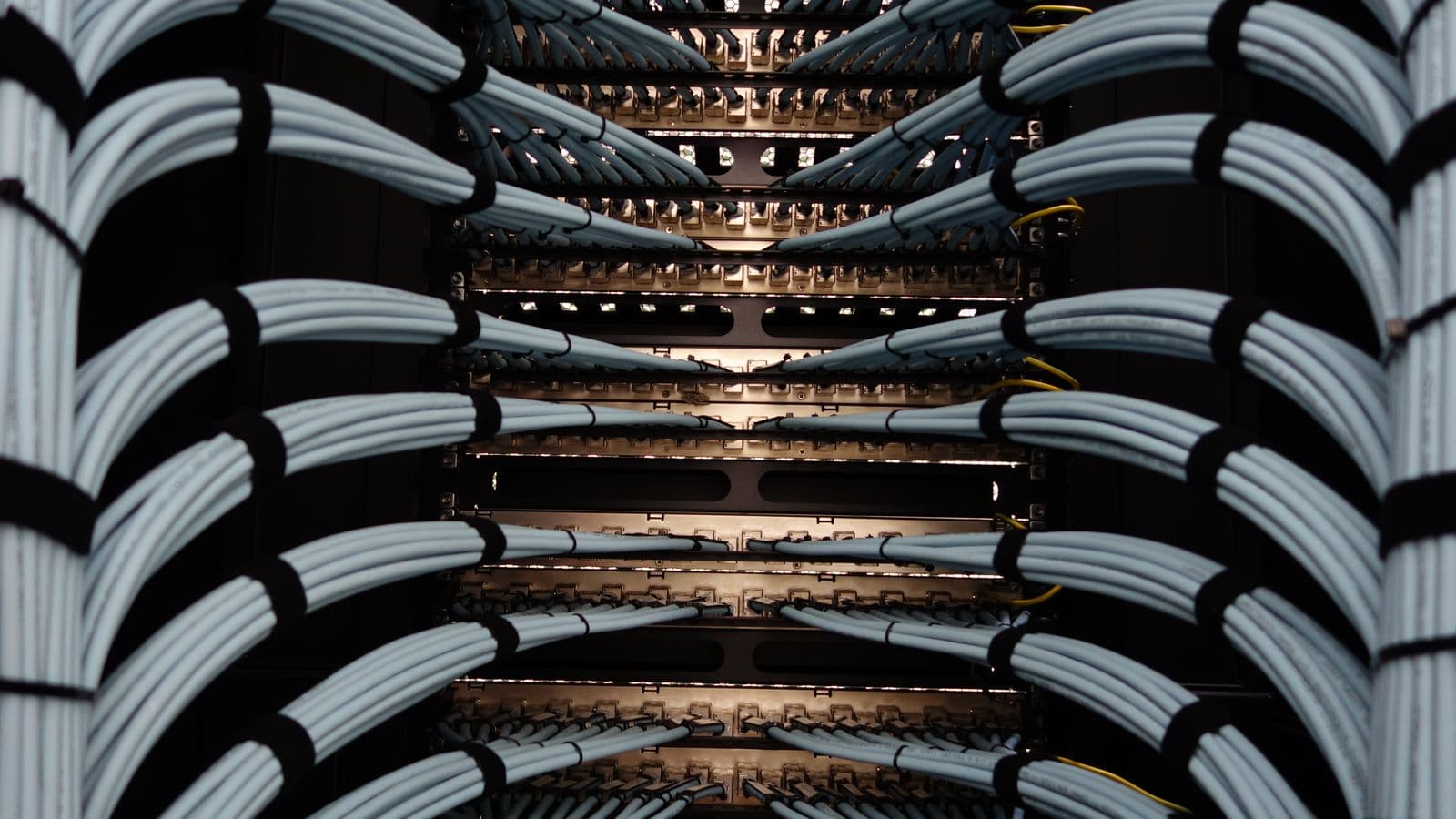
Choosing a cable support system in a factory looks like a secondary decision at first glance, but a poorly chosen cable tray or ladder comes back over the life of the facility as overheating, electromagnetic interference and expansion constraints. The choice between cable tray, ladder and conduit is an engineering decision driven by load type, ambient conditions and future expansion needs, not a matter of aesthetics or cost alone. This guide covers the selection criteria for cable support systems in industrial plants, how to calculate fill ratio, and the installation mistakes we see most often in the field.
Tray vs. Ladder vs. Conduit
All three systems physically protect cable and define its route, but each fits a different use case:
- Cable tray: A solid-bottom or perforated-bottom carrier with side rails. Preferred where a large number of cables need to run together, tidily and accessibly, panel runs, main distribution routes.
- Cable ladder: Two side rails joined by cross-rungs, with an open bottom. Preferred for heavy, thick-section power cables, especially on long straight runs and points requiring good ventilation.
- Conduit: Carries a single cable or a small number of cables with the highest level of mechanical protection. Preferred for underfloor crossings, moving zones near machinery, and areas with explosion or fire risk.
These three systems are usually combined within a single facility, ladder or tray on the main routes, conduit or flexible tray closer to the machine.
Selection Criteria
The right system is determined by weighing these criteria in order:
- Cable type and cross-section: Thick-section power cables cool better on a ladder; thin-section control and signal cables are carried more tidily in a tray.
- Ambient conditions: Dusty, damp or chemical-vapor environments call for enclosed tray or conduit; clean, well-ventilated areas are fine with an open-bottom ladder.
- Mechanical risk: Areas exposed to forklift traffic, falling material or impact risk need conduit or reinforced tray.
- Heat management: High-current power cables need to dissipate heat, so they belong on open-bottom systems (ladder) or perforated trays, an enclosed tray traps heat and effectively lowers the cable's current-carrying capacity.
- Expansion margin: Given future cable needs, initial installation should start below fill-ratio capacity, not at it.
Calculating Fill Ratio
Fill ratio in cable tray and ladder systems is decisive for both heat management and future expansion room. The generally accepted approach is that cable bundles should not exceed 40-50% of the tray's cross-sectional area, a margin that leaves room to add cable later while keeping heat dissipation within the bundle adequate. Fill ratio should be calculated not just against today's cable count but the expansion the project anticipates. An overfilled tray causes even correctly sized individual cables to carry less than their rated current due to grouped heating, this ties directly into the group-installation correction factors under TS HD 60364-5-52.
Separating Power, Control and Signal Cabling
Running different cable categories in the same tray is one of the most common, and most consequential, installation mistakes. Power cables generate an electromagnetic field while operating; that field can induce interference and misreadings in nearby control cables and especially signal cables (analog measurement, communication lines, sensor signals). As a result:
- Power cables should run in their own tray or ladder.
- Control cables (24V DC, relay signals) should run on a separate route or tray, kept at a minimum separation distance from power cables.
- Signal and communication cables (Ethernet, RS485, 4-20mA analog) are the most sensitive category, use shielded cable where possible, and keep them at the greatest distance from power cables, ideally in their own tray.
- Where routes must run in parallel, a metal separator between them reduces the interference effect.
Skip this separation, and unexplained intermittent faults can show up in a production line's automation system, one of the hardest fault types to diagnose, precisely because its source sits in the cable routing rather than the equipment.
Mechanical Support and Hanger Spacing
Cable tray and ladder must be supported frequently enough that neither the system's own weight nor its cable load causes sag. Support spacing depends on tray/ladder width, material thickness and cable load, and should come from the manufacturer's catalog, as a general rule, 1.5-2 meter intervals are common under standard loads, tightening under heavy cable load. Inadequate support leads over time to sagging, strain on cable armor, and added mechanical stress at connection points. At turns in the route (T-junctions, elbows), the manufacturer's minimum bend radius must be respected, forcing cables, especially thick power cables, below their allowed bend radius can damage insulation.
Fire Resistance and Compartment Crossings
Cable routes need special attention where they cross fire compartment boundaries. A cable tray or conduit passing from one fire compartment to another must be sealed at the crossing point with fire-rated fill material, otherwise the cable route can act as a "chimney" that helps fire spread rapidly between compartments. This detail is frequently missed at the design stage and only caught during a fire inspection; retrofitting it afterward costs far more than planning it in from the start.
Labeling and Accessibility
When designing cable tray and ladder routes, plan for how access will be maintained during maintenance and troubleshooting. A route squeezed between dense equipment with no access makes adding or replacing a cable later nearly impossible. Permanent labels along the route, identifying which cables run there and any voltage-level warning, should appear at regular intervals, particularly important for maintenance-crew safety at points where power and signal cabling run close together. The general cabling-strategy principles here align directly with the approach we apply in our machine-line installation service.
Material Selection: Galvanized, Stainless, Polymer
Tray and ladder material should be chosen against ambient conditions. Hot-dip galvanized steel provides adequate corrosion resistance in most dry industrial environments; damp, chemical-vapor or frequently washed-down environments, such as food production, call for stainless steel or polymer (fiberglass-reinforced) systems instead. Choosing the wrong material leads to corrosion-driven structural weakening and cosmetic degradation within a few years, premature rusting of galvanized tray in wet-floor production areas is a common failure we see in the field.
Cable Bundling and Tie-Down Practices
Tidy bundling of cables inside a tray or ladder isn't purely cosmetic, it matters for both heat management and future maintenance ease. Overtightened cable ties compress the cable jacket and can create localized hot spots; ties should be snug enough to hold the bundle without pinching the jacket. Where different cable categories are forced to share a tray, they should at minimum be bundled into physically separate groups within it, ideally with a metal separator between them. Leaving extra slack at turning points also makes it far easier to reach a test point during a future fault without disconnecting the cable, a small detail that significantly shortens maintenance time.
Additional Criteria for Outdoor and Underground Runs
Additional requirements apply when a cable route leaves the building or runs underground. Outdoor tray and ladder systems need UV resistance and a higher IP rating (typically IP65 or above); since galvanized steel can corrode outdoors over time, long-term outdoor installations call for heavier hot-dip galvanizing or stainless steel. For underground crossings, cable isn't buried directly, it goes inside impact- and crush-resistant conduit, with warning tape or marker plates placed at intervals along the route so future excavation work can spot the line. Skip this precaution, and cable damage from a digger during a later infrastructure project is a common accident.
Common Mistakes
- Running power, control and signal cables in the same tray: Causes unexplained intermittent faults in automation systems.
- Pushing fill ratio above 50%: Causes cables to run below rated current due to grouped heating.
- Installing at full capacity with no expansion margin: Can force a complete route rebuild when new cable is needed.
- Exceeding manufacturer-recommended support spacing: Leads to sagging and mechanical stress at connection points over time.
- Not sealing fire-compartment crossings with fire-rated fill: Turns the cable route into a fire-spread path.
- Choosing material unsuited to ambient conditions: Using galvanized systems in damp or chemical environments causes premature corrosion.
FAQ
Should I choose cable tray or cable ladder? Tray for thin-section control/signal cables and routes needing a tidy appearance; ladder for thick-section power cables and long straight runs needing good ventilation.
Why shouldn't fill ratio exceed 50%? To leave room for future expansion and ensure adequate heat dissipation within the cable bundle, an overfilled tray causes even correctly sized cables to carry less than their rated current.
Why shouldn't power and signal cables share a tray? The electromagnetic field power cables generate can induce interference and misreadings in nearby sensitive signal cables (analog measurement, communications).
How often should cable tray be inspected? As part of periodic maintenance, at least once a year, checking for mechanical damage, sagging, corrosion and fill ratio.
When should conduit be used instead? For underfloor crossings, moving zones near machinery, or points with high mechanical impact risk, conduit offers cable the highest level of protection.
What precaution is needed at fire-compartment crossings? The point where tray or conduit crosses the compartment boundary must be sealed with fire-rated fill material, otherwise the route can help fire spread between compartments.
How do you add capacity to an existing tray? Once the fill-ratio limit is reached, either add a parallel new tray or review the existing bundle and remove unused or unnecessary cables to free up space.
How much does material choice affect cost? Stainless steel or polymer systems cost more upfront than galvanized steel, but the cost of early replacement from using galvanized in an unsuitable environment often exceeds that difference.
Conclusion
Choosing cable tray and ladder is an engineering decision industrial facilities shouldn't treat as an afterthought, done right, it reduces overheating risk, improves automation reliability and makes future expansion easier. SOREAS plans and installs cable support systems across Bursa's industrial facilities on an engineering basis, from fill-ratio calculations through power/signal separation.
Let's talk through this together
The SOREAS engineering team can assess what's covered here for your specific facility. Reach out via the contact form or call us directly.